


 English
 русский
 عربى
 Español

Industry News
Understanding the Structural Differences Between Gate Valves Types
Gate valves are a fixture of industrial piping. They're simple to operate and good at controlling flow, so you'll find them in water supply networks, oil and gas facilities, chemical plants, power stations and plenty of other places. They all serve the same basic purpose, yet their structures can differ a lot.
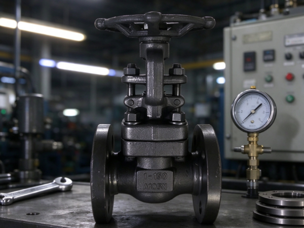
Those differences change how a valve opens and closes, how its internal parts move and how it fits a given piping layout. Some designs use a rising stem, while others keep the stem in place during operation. Gate shapes and seating structures vary too, and each combination has its own character.
Engineers, equipment buyers and maintenance teams benefit from knowing these differences. They also explain why different Gate Valves Types end up in different working environments.
What Are the Main Structural Components of a Gate Valve?
A gate valve rests on a simple principle. A movable gate slides between two internal seating surfaces to control the passage of fluid. When the gate moves clear of the flow path, the valve is open. When it moves into the closed position, it blocks the passage.
The overall design looks similar across many models, but each component has its own role in how the valve works.
The main structural components are:
- Valve body: The main outer housing. It connects to the pipeline and holds the internal parts that control flow.
- Gate or disc: The movable part that travels across the flow passage. Its shape and construction help tell gate valve designs apart.
- Valve stem: The component that carries movement from the operating mechanism to the gate.
- Bonnet: The upper cover of the valve body. It encloses the internal operating parts and gives access for inspection or maintenance.
- Seat: The internal surface the gate closes against. How the gate and seat meet affects how well the valve stops flow.
- Operating mechanism: The handwheel, gear arrangement or other device that moves the valve between open and closed.
These parts work together, but they aren't arranged identically in every gate valve. The stem may rise as the valve opens, or it may turn without visibly changing its outside position. The gate itself may be solid, flexible or parallel.
Those variations produce several categories of gate valve. Some classifications look at stem movement, others at gate shape or seating design. The categories can overlap, because they describe different parts of the same valve.
How Does a Rising Stem Gate Valve Differ Structurally?
On a rising stem gate valve, the stem moves up or down as the valve operates. Open the valve and the stem rises. Close it and the stem goes back down.
That motion is the design's most recognizable feature. Because the stem is connected to the gate, its position shows roughly what state the valve is in. Operators can often tell open from closed just by seeing how far the stem sticks out above the bonnet.
The structure normally includes a stem arrangement that allows vertical travel. The operating mechanism turns the stem, and the stem-to-gate connection converts that turning into the gate's upward or downward travel.
Several structural traits mark this design:
- Visible stem movement: The stem extends above the valve as the gate rises.
- External position indication: Operators can check the stem position without depending entirely on a separate indicator.
- Space above the valve: The exposed stem length changes during operation, so extra clearance is needed.
- Stem protection: The exposed section may need shielding from dirt, impact or environmental conditions.
This design helps where visual confirmation of valve position matters. The headroom it needs should be part of pipeline planning, though. Where overhead clearance is tight, the moving stem can cause installation problems.
Maintenance deserves attention as well. The exposed stem should stay clean and free of damage that could interfere with its movement.
Why Do Non-Rising Stem Gate Valves Have a Different Internal Arrangement?
A non-rising stem gate valve works differently. Its stem rotates during operation but doesn't move noticeably up or down. The gate travels inside the valve body while the outside stem stays put.
To make that possible, the stem and gate use a different connection. The stem passes rotation to the gate, which then moves along the internal flow passage without the stem rising above the bonnet.
The result is a more compact outside profile. That helps in underground pipelines, utility systems and installations short on vertical space.
Its main structural features:
- Fixed external stem position: The stem doesn't extend upward as the valve opens.
- Internal gate movement: The gate moves inside the body while the stem rotates.
- Compact installation profile: It doesn't need the overhead clearance a rising stem valve does.
- Less direct visual indication: Operators can't read the gate position from how far the stem sticks out.
Checking valve position takes more care with this design. With no clear visual cue from the stem, operators may need operating records, position indicators or other inspection methods.
The internal stem-to-gate connection matters too. Wear, contamination or damage there can affect how the gate moves. Maintenance planning should cover the internal operating arrangement, not just the outside appearance.
What Is the Difference Between Solid Wedge and Flexible Wedge Gate Valves?
Gate shape and construction offer another way to classify these valves. Solid wedge and flexible wedge are common examples. Both use a wedge-shaped gate, but their insides differ.
A solid wedge gate valve has one rigid gate. The structure is fairly simple. The gate moves between the seats and forms a closing surface once the valve is shut.
The solid design is often chosen where a simple internal arrangement will do. Since the gate is rigid, though, it can't adjust much to small differences between the seating surfaces.
A flexible wedge gate valve has a gate built to allow some controlled movement or deformation. That lets the gate respond to slight changes in how the seating surfaces relate to each other.
The difference shows up in several structural features:
| Structural feature | Solid wedge gate valve | Flexible wedge gate valve |
|---|---|---|
| Gate construction | One rigid piece | Designed with a degree of flexibility |
| Response to seat movement | Limited adjustment | Can accommodate some variation |
| Internal structure | Relatively simple | Includes a flexible gate design |
| Design consideration | Depends on the alignment of the seating surfaces | Allows some adaptation to changes in the valve structure |
The choice depends on the operating environment and the piping system's requirements. A solid wedge can suit places where the internal arrangement stays stable. A flexible wedge makes sense where some give between gate and seats is useful.
Neither design fits every application. Valve body, materials, fluid conditions and maintenance needs all play into the selection.
How Are Parallel Gate Valves Structurally Different From Wedge Gate Valves?
Parallel gate valves use a different gate arrangement. Rather than a wedge-shaped gate fitting between angled seats, the parallel design has flat, parallel closing surfaces.
That changes how the gate meets the seats. In a parallel gate valve, the gate slides between the seating surfaces and closes the passage by touching the matching flat surfaces. Depending on the design, it may use separate gate elements or other internal arrangements.
A wedge gate valve uses angled surfaces. As the gate moves to the closed position, the wedge shape helps make contact with the seats. The geometry of the gate is central to the closing action.
The main structural differences:
- Gate shape: Wedge valves use an angled gate, while parallel designs use parallel closing surfaces.
- Seat arrangement: Wedge designs have seating surfaces matched to the angled gate. Parallel designs use opposing parallel surfaces.
- Closing action: Gate and seat geometry set how contact forms when the valve closes.
- Internal movement: Both designs move a gate across the flow passage, but they make contact differently.
These differences affect the valve's design and its fit for particular operating conditions. A parallel gate may be considered where its seating arrangement suits the system. A wedge design may be picked where its closing mechanism suits the job.
When comparing the two, buyers should look past the outside shape. The internal gate and seat arrangement is what defines the structural difference.
What Makes Resilient Seated Gate Valves Different?
Resilient seated gate valves differ from traditional metal-seated designs because the gate carries a resilient material on its contact surface. That material commonly forms the sealing interface between the gate and the valve body.
The gate still moves across the flow passage, but contact works differently. Instead of relying only on metal-to-metal contact, the resilient material helps seal the valve when it closes.
This design is often tied to water distribution and utility systems. Its structure aims to give a closing arrangement that suits conditions in those applications.
Several features define this type:
- Resilient gate surface: A flexible material covers the gate's sealing area.
- Different seat contact: The resilient surface meets the matching internal area when the valve closes.
- Protected internal surfaces: The design can reduce direct contact between some metal surfaces and the fluid.
- Material-related considerations: The resilient material must be compatible with the fluid and operating environment.
The sealing material is a key part of the design. It should be judged against fluid composition, temperature conditions and the chance of wear or aging.
Don't confuse resilient seated valves with flexible wedge gate valves. The terms describe different structural traits. Flexible wedge refers to how the gate itself is built, while resilient seated describes the material at the sealing interface.
How Do Gate Valve Bodies and Bonnets Differ?
The body and bonnet make up the valve's main outer structure. They may look alike across models, but their design can vary with the intended application, installation environment and maintenance needs.
The body houses the gate and connects the valve to the pipeline. Its internal shape decides how the gate fits within the flow passage. The outer body also has to hold the operating parts and keep the required structural integrity.
The bonnet covers the top of the body. It houses the stem arrangement and helps enclose the internal components. Different bonnet structures change how the valve is assembled, inspected and maintained.
Common structural differences include:
Bolted bonnet design
A bolted bonnet joins the bonnet to the body with fasteners. This gives a clear connection between the two main sections, and it can allow access to internal parts when maintenance is needed.
Welded bonnet design
A welded bonnet is joined to the body by welding. That makes a permanent connection, not one you open by removing fasteners. It may be considered where a fixed enclosure is appropriate.
Pressure seal bonnet design
A pressure seal bonnet uses internal pressure to help keep the seal between bonnet and body. Its structure differs from a conventional bolted joint and is linked to particular industrial valve applications.
Treat the body and bonnet as one connected structural system. Their design affects internal space, assembly, access and how the valve fits into the wider pipeline.
For maintenance teams, the bonnet connection matters most. It decides how internal components can be reached and what procedures inspection or repair may require.
Which Structural Differences Matter When Selecting a Gate Valve?
Choosing a gate valve takes more than naming its general category. Two valves can both be called gate valves and still have different internal arrangements, operating methods and maintenance needs.
A practical selection process weighs structural features against the conditions of the piping system.
These points can guide the comparison.
Stem arrangement and installation space
A rising stem valve needs clearance above the bonnet while the stem moves. A non-rising stem design has a more compact outside profile. Installation space, accessibility and the need for visible position indication can all influence the choice.
Gate shape and closing arrangement
Solid wedge, flexible wedge and parallel gate designs have different internal structures. Their suitability depends on how the gate interacts with the seats and how the valve will operate in the intended system.
Seating material
Metal-seated and resilient seated valves have different contact surfaces. The choice should reflect the fluid, the operating environment and maintenance expectations.
Body and bonnet construction
The body-bonnet connection affects assembly and access to internal components. Buyers should think about how the valve will be inspected and maintained after installation.
Operating method
The operating mechanism should suit the valve's size, location and expected use. A handwheel may do for some installations, while others need a gear mechanism or an actuator.
Maintenance access
Some valves are easy to inspect from outside, while others need attention to internal components. Available maintenance space and the expected inspection process should be considered during selection.
A comparison table can help organize these factors before a purchase decision:
| Selection factor | Structural question | Why it matters |
|---|---|---|
| Stem design | Does the stem rise during operation? | Affects clearance and position indication |
| Gate construction | Is the gate solid, flexible or parallel? | Determines the internal closing arrangement |
| Seating design | Does the valve use metal or resilient seating? | Influences sealing contact and material compatibility |
| Bonnet connection | Is the bonnet bolted, welded or pressure-sealed? | Affects enclosure and maintenance access |
| Operating mechanism | How is the gate moved? | Determines how the valve can be operated |
| Installation environment | Is there enough room around the valve? | Helps avoid access and operation difficulties |
Understanding these differences gives buyers and engineering teams a firmer basis for comparing gate valves. It also guards against a common mistake: treating all gate valves as structurally identical because they do the same general job.
The best design depends on how the valve's internal construction, the pipeline layout, the fluid being handled and the maintenance conditions fit together. Looking at those factors as a whole makes it easier to find a valve structure that meets the real needs of an industrial system.
Recommended Products
The variety of models, to meet the development needs of various regions in the world.
Copyright © ZHEJIANG ROCK VALVE CO., LTD.

Cast Steel Valves Stock Wholesaler